Leonardo da Vinci’s, universal genius of the 15th
century notebooks contain sketches and a description
of two self – indicating weighing mechanisms, one
being semi – circular in form, the other triangular.
The models were constructed by the research department of W.&T. Avery Ltd working from the sketches from Leonardo ‘s notebooks, preserved in Paris.
The models were constructed by the research department of W.&T. Avery Ltd working from the sketches from Leonardo ‘s notebooks, preserved in Paris.
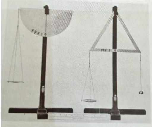
Although Leonardo da Vinci’s sketches of these mechanisms were essentially practical in
conception, no attempt seems to have been made to exploit the invention until 9th century.
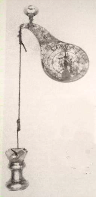
A simple pendulum balance patented in 1863 consisted of a
pendulum made from flat sheet brass and suspended from shackle
as shown in the figure. The load was applied by a cord and ring.
The circular pendulum weight formed a graduated scale at the
centre. When a load was suspended from the instrument, the
pendulum swung outwards to a position of balance and the pointer
indicated the correct weight. These little balances were made for
weighing letters and postal packages.
In chronological order, Richard Salter of
George Salter & Co.Ltd.,West Bromwich is
known to have been made a barrel spring
balance in the year 1770. At first, a
compression spring was used and later spring
balances incorporated tension springs.
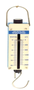
Augustus Siebel invented the bow spring balances in 19th century and
subsequently the elliptical spring balances in partnership with
H.Marriott.
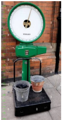
The latter form of resistant and indicator used in platform scale for many years and supplied to Railway companies by Henry Pooley.
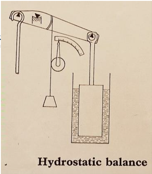
Hydrostatic balances were constructed as early as 1874 by Henry Pooley and some remained in use for many years.
The latter form of resistant and indicator used in platform scale for many years and supplied to Railway companies by Henry Pooley.
Hydrostatic balances were constructed as early as 1874 by Henry Pooley and some remained in use for many years.
The indicator consisted of a beam or lever, one end, which
was connected to a conventional load carrying system of a
platform scale or weighbridge as in the figure. From the
other end, a counter poise was suspended dipping in a tank
of water.
When a load was applied on the platform scale, the
counter poise was raised out of the water, losing part of its
buoyancy until a position of balance was found
automatically. In one version of the scale, an indicator was
driven from motion of the lever by means of a chain and
drum and the weight was thus read on a graduated chart.
